Pixelating Live with SVG
Published 2 years, 6 months pastFor reasons I’m not going to get into here, I want be able to pixelate web pages, or even parts of web pages, entirely from the client side. I’m using ViolentMonkey to inject scripts into pages, since it lets me easily open the ViolentMonkey browser-toolbar menu and toggle scripts on or off at will.
I’m aware I could take raster screenshots of pages and then manipulate them in an image editor. I don’t want to do that, though — I want to pixelate live. For reasons.
So far as I’m aware, my only option here is to apply SVG filters by way of CSS. The problem I’m running into is that I can’t figure out how to construct an SVG filter that will exactly:
- Divide the element into cells; for example, a grid of 4×4 cells
- Find the average color of the pixels in each cell
- Flood-fill each cell with the average color of its pixels
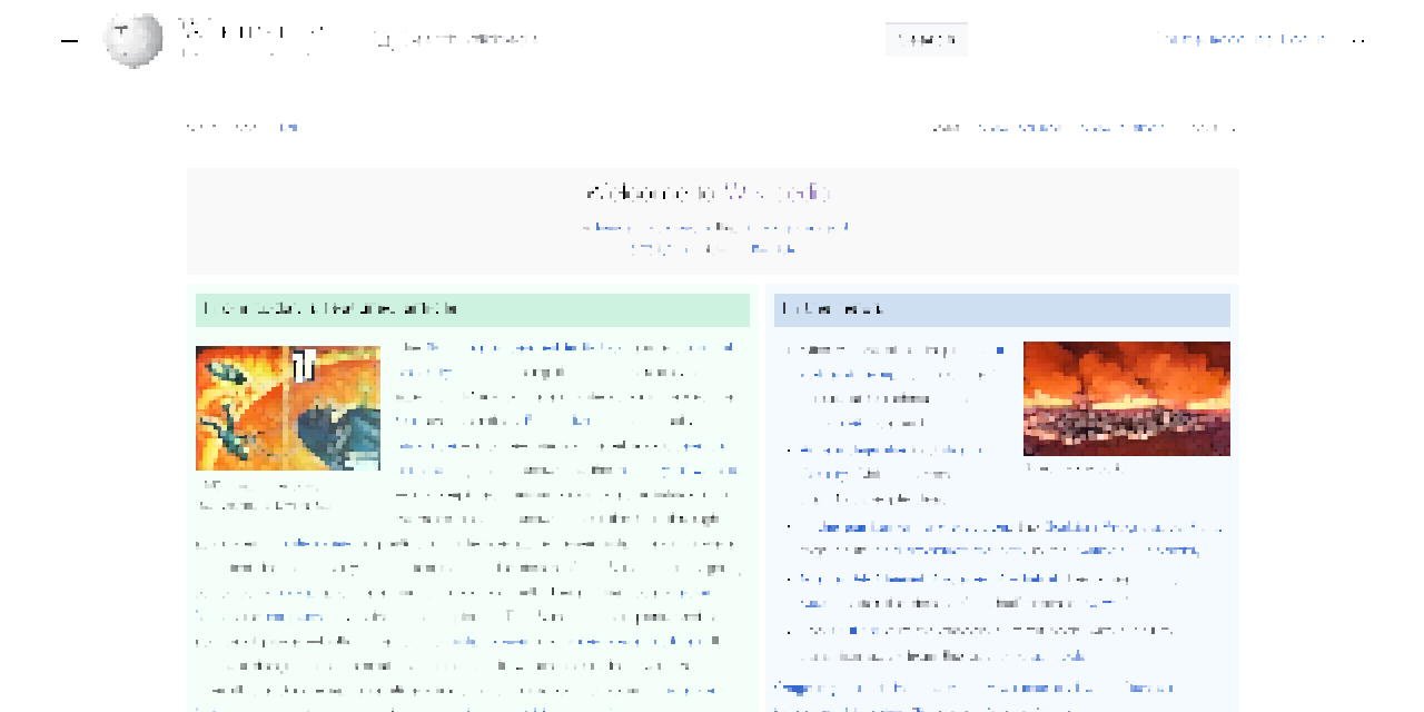
As a way of understanding the intended result, see the following screenshot of Wikipedia’s home page, and then the corresponding pixelated version, which I generated using the Pixelate filter in Acorn.
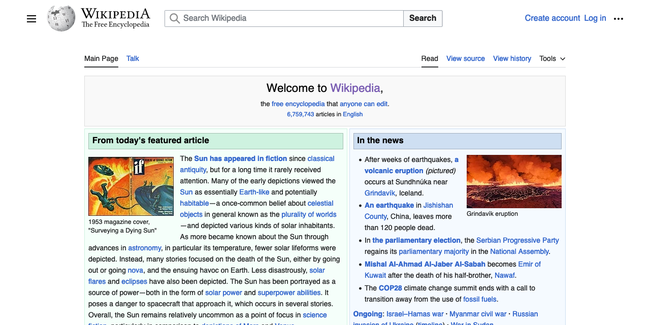
See how the text is rendered out? That’s key here.
I found a couple of SVG pixelators in a StackOverflow post, but what they both appear to do is sample pixels at regularly-spaced intervals, then dilate them. This works pretty okay for things like photographs, but it falls down hard when it comes to text, or even images of diagrams. Text is almost entirely vanished, as shown here.
I tried Gaussian blurring at the beginning of my filters in an attempt to overcome this, but that mostly washed the colors out, and didn’t make the text more obviously text, so it was a net loss. I messed around with dilation radii, and there was no joy there. I did find some interesting effects along the way, but none of them were what I was after.
I’ve been reading through various tutorials and MDN pages about SVG filters, and I’m unable to figure this out. Though I may be wrong, I feel like the color-averaging step is the sticking point here, since it seems like <feTile> and <feFlood> should be able to handle the first and last steps. I’ve wondered if there’s a way to get a convolve matrix to do the color-averaging part, but I have no idea — I never learned matrix math, and later-life attempts to figure it out have only gotten me as far as grasping the most general of principles. I’ve also tried to work out if a displacement map could be of help here, but so far as I can tell, no. But maybe I just don’t understand them well enough to tell?
It also occurred to me, as I was prepared to publish this, that maybe a solution would be to use some kind of operation (a matrix, maybe?) to downsize the image and then use another operation to upsize it to the original size. So to pixelfy a 1200×1200 image into 10×10 blocks, smoothly downsize it to 120×120 and then nearest-neighbor it back up to 1200×1200. That feels like it would make sense as a technique, but once again, even if it does make sense I can’t figure out how to do it. I searched for terms like image scale transform matrix but I either didn’t get good results, or didn’t understand them when I did. Probably the latter, if we’re being honest.
So, if you have any ideas for how to make this work, I’m all ears — either here in the comments, on your own site, or as forks of the Codepen I set up for exactly that purpose. My thanks for any help!
Comments (18)
It seems that “fill each 4×4 cell with the average of its pixels” is a blending of 16 “fill each cell with its top-left” (the thing you mention as ‘a couple of SVG pixelators’), at 16 different offsets. Can you make something like that work? If the pixelator doesn’t naturally support an offset, it can be hacked in by translating the input, pixelating, then translating it back.
One thing that looks tricky at first is how to blend them, but at a minimum, you could use opacities of 100%, 50%, 1/3, 1/4, 1/5, …, 1/16, back to front, and that should get you something with equal weight to reach layer.
(guy who thought an 8×8 adaptive quality JPEG compressor and SQIP vector LQIPs were good ideas to built – so take the following with lots of salt…)
SQIP could probably be made to do this.
But you could even go more barebones & slice the screenshot into desired block sizes (e.g. 8×8 like JPEG uses), then calculate the Mean color of each slice and then glue them back together again in order. I’ve abused the same nasty approach in “Adapt”. All of this can be done with ImageMagick/GM. And if it still needs to be a vector afterwards, potrace+svgo or SQIP/Primitive will convert the raster to vector successfully.
To add an extra step with the reverse command
erodewill get closer to the result:Demo link
“Scale down smoothly, scale back up crudely” is definitely the conceptually easiest way to do this, I’ve done similar things in Illustrator.
Searching the net for “pixelate svg filter” turns up a bunch of results that look good and use various methods.
The trick seems to lie in scaling back the dilation just enough to match the body font size. I’ve forked the pen to produce something close to the second screenshot.
I would recommend using a convolution filter thats just ones divided by number of elements. That gets you the averages and then you regularly sample the pixels with the pixelizer you didn’t like.
You can definitely do an average with feConvolveMatrix! It even has a divisor feature. So you just set the matrix to all ones and the divisor to the number of elements.
Check out this cool video on convolution matrices. It’s not normal matrix math it’s more of a window they slide across the image. Also the second part of this is good too if you want more.
Pingback ::
SVG实时像素化 - 偏执的码农
[…] 详情参考 […]
Can you use the
blurCSS function like this:Usage: Add the class
blurto body or other element you want blurred.Here’s the closest I could come up with:
https://codepen.io/dsmmcken/pen/rNRaOJE
It does a subtle blur, then a subtle sharpen, then repeats the middle pixel of a 3×3 grid. Happy holidays!
Reduce your feFlood height and width to 1. You only want to pick one pixel out of each 4×4 block.
If you want to, you can do the 4×4 convolve to get the average of the block:
feConvolveMatrix kernelMatrix=”1 1 1 1 1 1 1 1 1 1 1 1 1 1 1 1″ order=”4″ result=’convolve’
feComposite in=’convolve’ in2=’tiles’ operator=’in’
I don’t get SVG filters well enough to figure out the entire thing, but if you want to do box-blurring through convolutions, all you need is a correctly sized kernel of all 1s. Gaussian blurring is just convolving with a gaussian distribution kernel, but the way I understand it you end up sampling the blurred result, so a box blur with the same radius as the pixelization should be what you want.
I’ve managed to construct a solution that performs a proper average, while managing to avoid rounding artifacts in Firefox and Chromium. The basic idea is that we use one or more
<feConvolveMatrix>s to compute the average color of each cell, placing it in the cell’s top-left corner. Then, we use a special<feDisplacementMap>to flood each cell with the top-left pixel. The special displacement images are computed dynamically, so that the solution works for any cell size. The output isn’t 100% consistent (in fact, it differs between browsers), since the average for each cell includes a bit of color from the pixels of adjacent cells, but it’s about as close as you can get using the noisy<feDisplacementMap>.To adjust the cell size, set the
widthandheighton the two<feImage>s to the cell size, and set thescaleon the<feDisplacementMap>to twice the cell size. Thewidths andheights inside the embedded SVG images should be set to any value greater than or equal to the cell size; setting them less than the cell size may cause rounding artifacts. Then, set theorderof the<feConvolveMatrix>to the cell size, and make sure the number of1s in thekernelMatrixmatches the cell size squared. ThekernelMatrixcan get pretty big for large cell sizes, so I wrote up a Python script to split it into several<feConvolveMatrix>operations based on the prime factors of the cell size.This comment by rikroots on HackerNews pointed me to this CodePen by Taylor Hunt.
I’ve adjusted the parameters a little to give a better result for your specific example, but it’s wonderfully simple and gives great results:
Nice work!
Follow your idea, I found a solution: Codepen
Do the AVG calculation with a 3*3
<feConvolveMatrix>.Filter the
SourceGraphicwith tiled<feImage>.Scale it up with a
radiusoffeImage.size / 2The pixelating scale can be controlled by
sizeof<feImage>I think this topic – “Pixelating Web Pages for Undisclosed Reasons” – deserves one possibly important side note: in case those undisclosed reasons involve concealing potentially sensitive information, then pixelation alone is not a suitable means at all, since it is possible to reconstruct original text from its pixelated representation.
In short: individual character combinations produce pretty unique groups of “average pixels” shades [1]. It is indeed OK for creating thumbnails or previews of non-sensitive text (for example when concrete text could draw too much attention away from overall design), but not for “redacting out” text content.
When information security comes to play, it’s way safer to physically alter (“scramble”, “destructively obfuscate”, “greekize” [2]) source data before consecutive visual processing.
[1] Nice visual explainer and POC: unredacter by Dan Petro.
[2] Before learning these terms, I’ve referred to this process as “dummyzation”, hence dummyze – bookmarklet that walks the DOM and replaces all visible characters with
▒.It actually isn’t meant for obscuring sensitive data, myfonj, but that’s a really good and (as you say) important observation. Thank you!